The SL300 PC Programmer
The SL300 PC Programmer
This free tool is upgraded with each release of a SL series module. New modules are coming soon.
When used with the SL332/SL335/SL340, it can set functions that are not available using the top mounted switches.
The SL300 Programmer can read and program all parameters for the entire range of Smart Line signal conditioners.
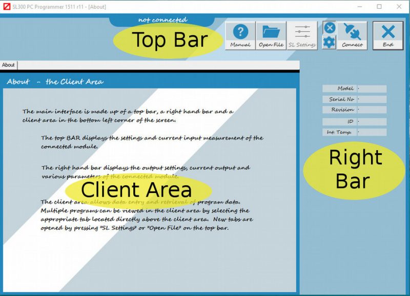
Main Screen Display
The top BAR displays input settings and input measurement of the connected module.
The right hand bar displays the output settings, output and various parameters of the connected module.
The client area allows data entry and retrieval of program data. Multiple programs can be viewed in the client area by selecting the appropriate tab located directly above the client area.
New tabs are opened by pressing SL Settings or Open File on the top bar.
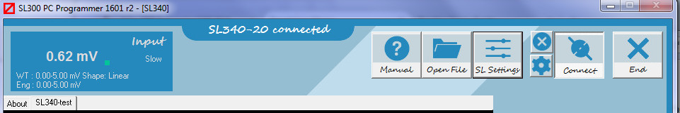
Top Bar Controls
SL300 Top Bar With a SL340 Connected
| Help | Open PDF documentation |
| Open File | Open a saved program from a previous session. |
| SL Settings | View/Modify user program details of the connected module. |
| Off | Close an open COM port. |
| COM | Select and connect to a COM port. |
| Connect | Open the last COM port used |
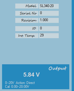
Right Bar Display
| Model | Part No of connected item |
| Serial Number | Serial of connected item |
| Revision | Firmware of connected item |
| Temperature | Temperature of internal processor |
| ID | User identification number |
Right Bar with SL340 Connected
The Client Area Display
SL700 Client Area with SL340 displayed
The client area has a tabbed interface and can retrieve previous programs from saved files (filename.sl3) or by reading the content of a connected SL series module.
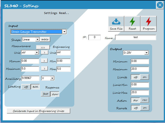
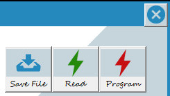
Common Controls on the SL Settings Screen
| Save | Save current settings to a file. |
| Read | Read settings off connected device. |
| Program | Program connected device |
| Close | Close this screen (loose changes?). |
SL700 Common Client Controls
Entry Parameters – vary with module number
| Input | Select Measurement type / Range or sensor |
| Range | Minimum to maximum of measurement unit. |
| Measurement Unit | Unit of measure that the range is calibrated. |
| Sensor | Input device external to the isolator measuring the parameter. |
| Shape | Linear = Direct relationship between measurement and reading. Table = A correction table is applied to correct errors in the input sensor. |
| Auxiliary | A power supply available to the input terminals used to power the sensor. |
| Loading | Resistance added across measurement terminals to reduce noise or bias inputs. |
| Response | Time taken for input measurement to be reflected in the output. The Fast / Slow response function is input filtering to reduce jitter in the measurement. |
| Engineering Unit | In many cases it is the same as the measurement unit however the measurement unit can be rescaled into a user unit that more closely represents the process being measured. |
| Engineering Min | Minimum process value that corresponds to the minimum measured unit value. |
| Engineering Max | Maximum process value that corresponds to the maximum measured unit value. |
| Input Type | Standard = Input is measured between the input and return terminals. Differential = Input is the difference between two measured values. |
| Action | Direct = The output rises from minimum to maximum as the input rises from minimum to maximum.Reverse = The output falls from maximum to minimum to as the input rises from minimum to maximum. |
| Signal Limits | When available HIGH and LOW limits can be set over the entire output signal range. |
Linearisation Tables (Shape)
Standard signal isolators produce a linear output in response to a linear input. This means that when plotting output against input on a line chart the result would be a straight line.
SL300 plots input on the vertical axis and output on the horizontal axis. Many measurement applications require the input output response to be tailored to correct errors in the linearity of the measured signal.
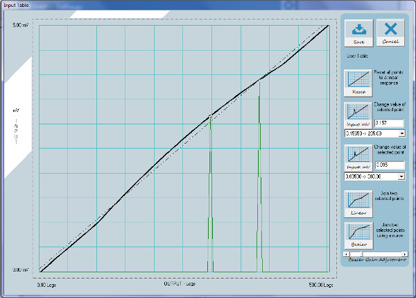
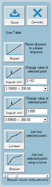
Edit Linearisation Table
The SL series uses look up tables to linearise errors in the industry standard probes and provides this facility on the generic measurement ranges for you to correct errors in unusual probes or errors in your process parameter. When creating a user specified range;
- The horizontal axis is broken up into 101 equally spaced points that represents the output in engineering units.
- The vertical axis represents the input in measurement unit.
- The output point values cannot be changed, the input measurement to produce the output value is the parameter that is changed.
- Each progressive input value MUST be greater than the last.
Editing of each input point is accomplished by clicking on the chart or selecting the points from the drop down lists. Two drop down lists enable the selection of two points at once which then can then be joined either as a straight line or using the simple bezier function to curve above or below average using the bezier gain slider.
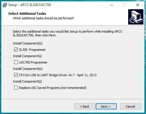
SL300/USC700 Programmer Setup
SL300 Programmer is free software used to configure and customise APCS SL series signal conditioning modules.
- System Requirements: Microsoft Windows XP and above
- Interface Isolation module: Computer Adaptor COA703-02
All of the following are supplied from the one DOWNLOAD package SetupSL300_USC700-YYMMC.exe.
- SL300 PC Programmer
- USC700 Programmer
- USB driver (32/64 bit detected)
New versions of the install may be run without un-installing the old version.
Warning Hazardous Voltages
We are 99.9% sure that if you connect an SL series module directly to a USB port on your PC or mobile phone no damage either device will occur. Communication will not occur without the COA703 connected.
The SL devices are isolators. The SL300 interface connector is in most cases at the negative input measurement potential. This means that connecting to the unit must be via the COA703. The COA703 provides 2KV isolation, enabling safe operation while the unit is connected to an operating system.
The SL series is used in industrial environments, its +/- input terminals or +/- output terminals may be at elevated voltages to enable your application to work. Servicing on site should only be conducted by qualified personnel that are familiar with the installation. Application Package and Driver
SL332 Additional Functions
SL332 has extra features not documented on the data sheet as follows;
Output Full Scale Check
While input code switch is in position 0 the output will go to full scale of the range selected on the output code switch. The output full scale value for each setting is found on the data sheet.
Remote Control Output
The output can be remotely controlled by the SL300 module when the input switch is set to F and the output switch is set to D.
Signal Limiting
The customised output range has signal limiting that can be set using the SL300. This signal limiting is only in effect on the customised range (input and output switches on F) and if it has been enabled by the SL300.
SL335 Additional Functions
SL335 has extra features not documented on the data sheet as follows;
Output Full Scale Check
While input code switch is in position 0 the outputs will go to full scale of the range selected on the output code switches. The output full scale value for each setting is found on the data sheet.
Remote Control Output
When the input switch is set to F and the output switches are set to to D both outputs are remotely controlled.
When the input switch is set to F, output 1 is set to F and output 2 is set to D then output 1 follows the input and output 2 is remotely controlled.
Signal Limiting
The customised output ranges have individual signal limits. This signal limits are in effect on the customised ranges.
SL340 A Better Universal Isolator
Back in 1999 APCS invented the term Universal Signal Conditioner with the USC701. The unit was designed to replace all other transmitter types so a company could have one unit on the shelf to that could be programmed for the desired function before fitting.
In the market today there are many isolators that claim to have a universal input and cover many mV and temperature ranges.
In many cases these units work well on the specified ranges but when customising the ranges they may suffer from reduced range within the analogue to digital converter on the input or reduced use of the digital to analogue converter on the output. As a result the quoted accuracy will be reduced.
The SL340 has not been designed to replace the USC701. Today’s market requires cheaper isolators and converters that use less power and space. The SL340 represents what the market wants at a completive price.
The SL340 with only four input terminals supports Thermocouple, RTD, Strain Gauge, Resistance, Slide Wire and mV inputs without compromising accuracy.
The programmable input current and voltage sources each have two distinct ranges to maintain accuracy.
The input instrumentation amplifier can be configured as single ended or differential depending on the application. This amplifier has programmable offsets to ensure that the analogue to digital converter is always working over the widest possible range for the user’s input calibration.
Measurements are processed by the input side CPU, this dedicated processing ensures fast conversion to a digital signal that represents the user’s specified input calibration. This digital signal has been corrected to remove standard linearity errors produced by the sensor currently in use (TC, RTD, etc).
A digital data is sent from input to output via an an optical isolator. The output CPU contains an integrated digital to analogue converter and controls the switching of the output range components.
As isolation and output drive method does not rely on pulse width modulation conversion or linear conversion conversion methods no additional linearity and accuracy errors are introduced for a wide range of user defined calibrations.